
I posted on Facebook about a LED lamp I have, a G125 E27 11 W / 230 V 6000 K 1520 lm dimmable filament LED, that died.
Sorry, I don’t have time to write now, this is a machine translation of my Facebook post with with DeepL.com.
The lamp’s failure is an annoying little thing, but the manufacturer claims a lifetime of 15.000 h, in reality it lasted about 2.000 hours. I have also written that the lifetime of the best LED chips is under 10.000 h, the other half of this for the whole lamp is humbug. Then I wrote what Tibor Pálinkás, electrical engineer by training, wrote in an article that LED lamps typically fail due to electronic faults, typically due to heating and drying out of the electrolytic capacitors.
Now I had some time to relax and dismantled the dead LED. I simply smashed the 125 mm glass ball, then used pliers to cut off the excess glass (goggles and gloves are a must!) Perhaps it would have been more elegant to heat it with a tongs and cool it with water. Conventional fluorescent tubes can be cut up very nicely using this method, but this sphere had a very small neck and is filled with pressurised helium, so I preferred to use a hammer. A gentle toast with a geologist’s hammer was enough.
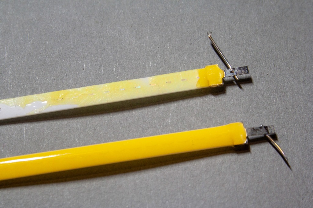
In the case, there are 4 filament LEDs, in a mixed connection, i.e. two or two are connected in parallel, and then the two are connected in series. Of the four LED strips, two are dead, simply broken, and two are working. One LED strip contains 25 LED chips on a white ceramic substrate, neatly arranged in a row (in the photo, those tiny shiny things in the middle of the strip, about 0.5×1 mm). The filament LED has a nominal opening voltage of 68 V (2.7 V per LED) and a current of 40 mA (calculated from the lamp power). In practice, it lights up at 64…66 V or 1…2 mA current, I measured 66 V at 10 mA current.
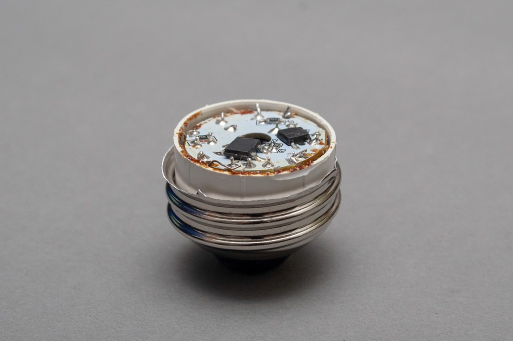
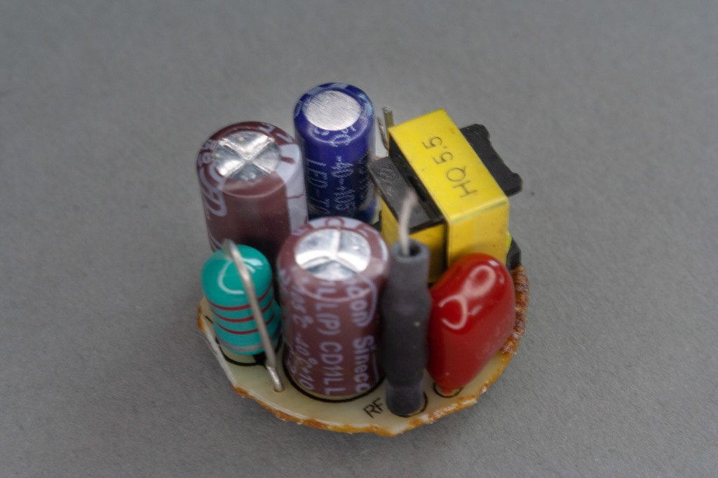
In production, the sealed wire protruding from the finished glass envelope was soldered to the electronics panel, a small plastic cap was placed on it and glued to the envelope together with the E27 (Edison threaded) metal cap. On disassembly, the bura was smashed and the glue was squeezed out, after which I got to the small Ø21 mm fibreglass PCB plate containing the electronics, which was hidden in the metal cap. The panel was partly SMD (surface mount) and partly THT (conventional). On close inspection with a magnifying glass it is quite obvious that it was assembled by hand soldering. Even the SMD components were soldered by hand, using conventional solder and tin (not SMD solder paste).
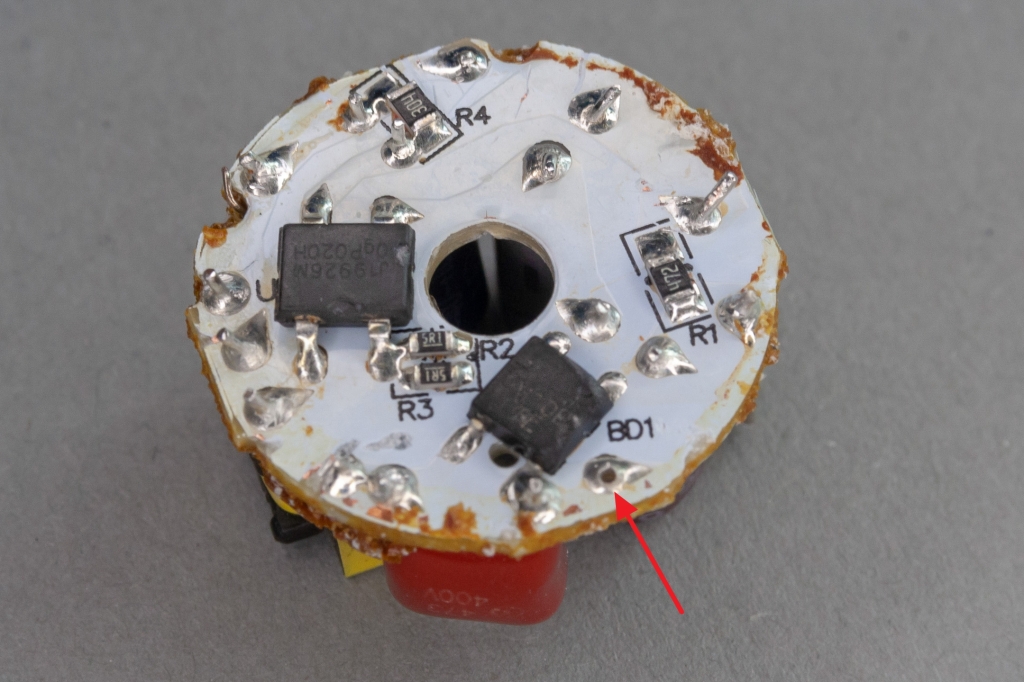
Well please, worthy believers! Imagine this factory, where industrious little hands are hand-crafting these tiny panels by the thousands, by the tens of thousands! Where’s the fairtrade!? As an individual, the soldering is also shoddy: for example, the RF resistor simply slipped out of place while I was fiddling with the panel. There is a small hole in its place (marked with a red arrow in the photo). This is a typical soldering fault that would have killed the lamp over time even if it had been in stock. (I have experienced this with other Chinese lamps.)
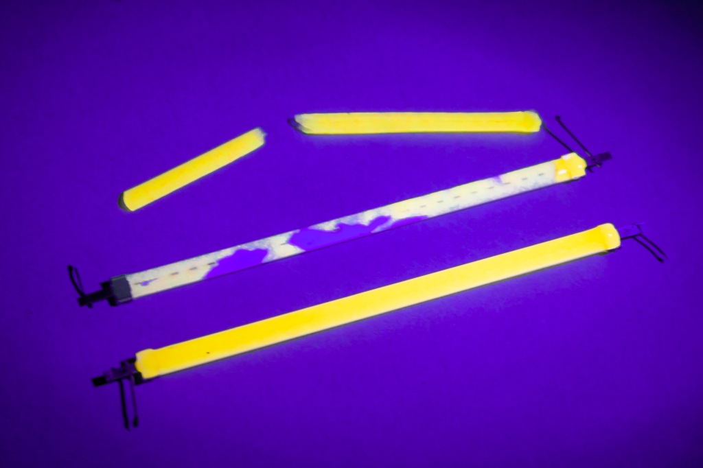
I took a bunch of pictures, you can have a look. In the last one, you can see that the silicone rubber coating on the filament (which I cut off one of them with a snicker) fluoresces yellowish in UV light. I thought I’d show you that too. The LED chips glow with a bluish UV light, the coating with a yellowish light, the two together become white. By the way, these lamps also have pretty decent UV emission, which I’ve observed before on a colored lampshade that had a nice fade on the inside where light hit it.


I took the electronics apart and redrew the not too complicated wiring. The 47 Ω series fusing resistor on the input was “slightly stretched”, I took it to be 67 Ω. It should dissipate 0.1 W, it shouldn’t heat up (of course, the shrink tube on it doesn’t help the heat dissipation). Otherwise it also serves as a fuse, it blows in case of a short circuit.
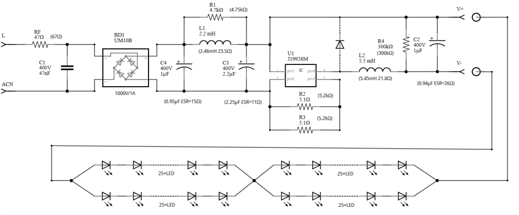
The measured values are given in brackets on the drawing.
However, I only measured the C1 47 nF noise filter capacitor inside at 7.1 nF, which is not good, but should not affect the lighting of the lamp. With the RF resistor in series with a noise filtering coil, and the C1 capacitor could be 100 nF (like in lamps made by Philips and Star Light), it might not interfere with DCF clocks and DAB radios in the area.
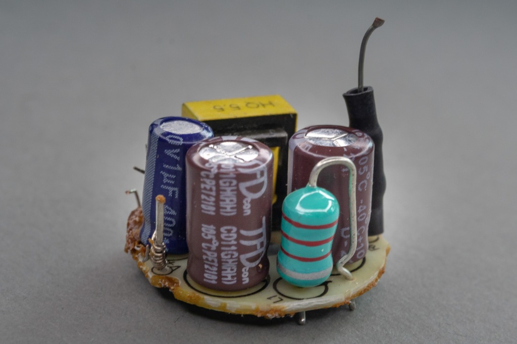
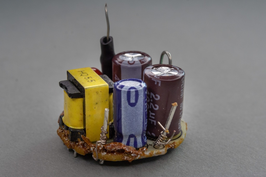
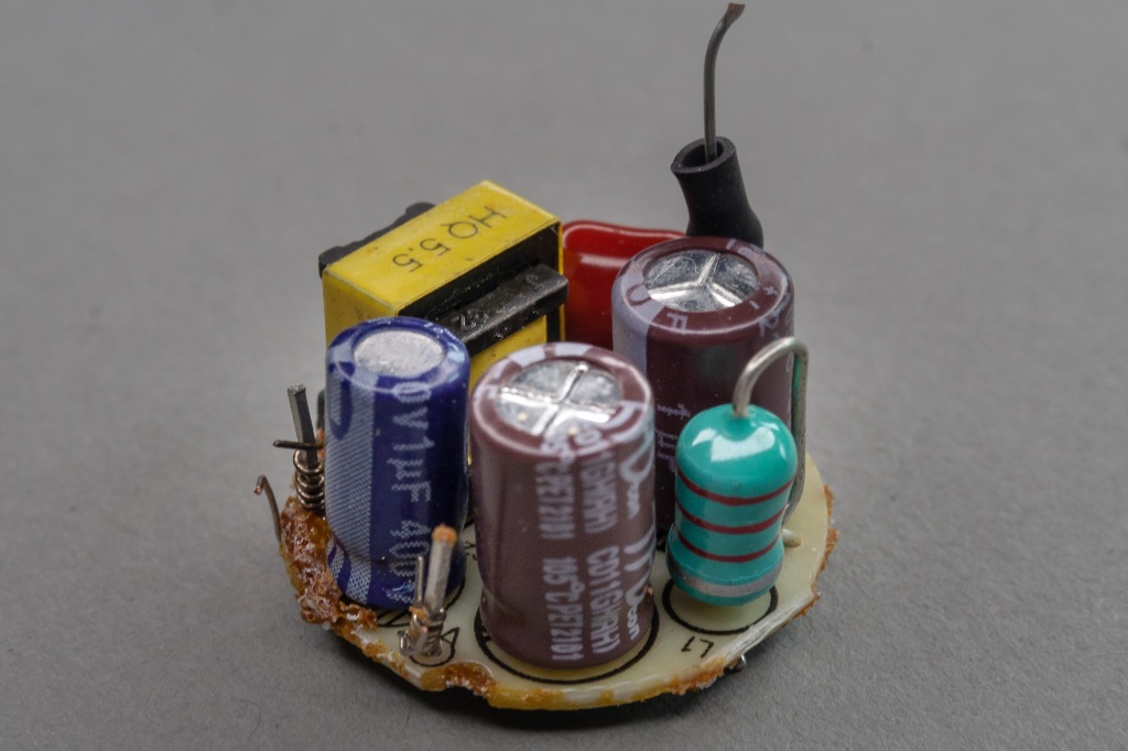
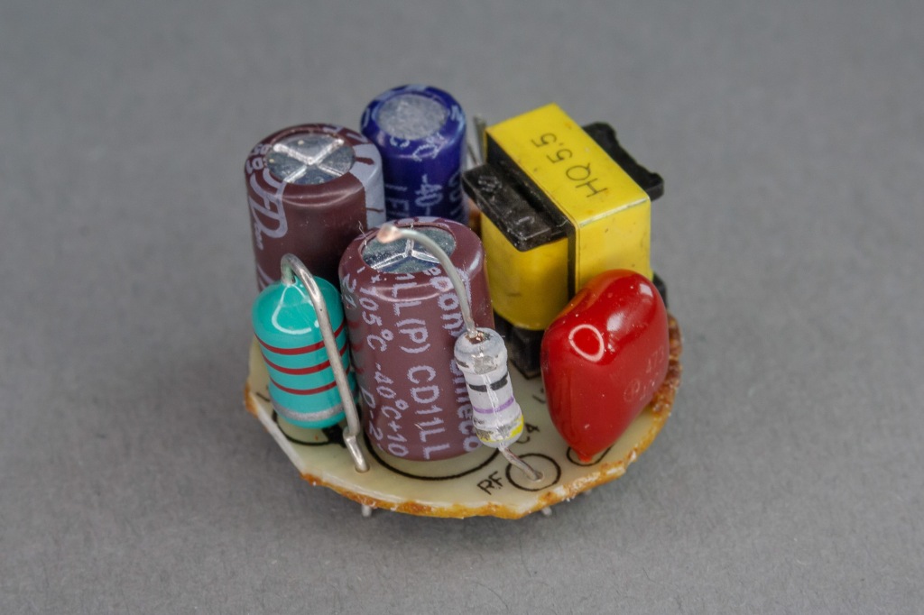
Next is the rectifier diode bridge, type UM10B, marked BD1, which is the smaller black box on the panel. The catalogue says it can handle 1000 V and 1 A current, which is OK. Then C4-L1-C3 is a filter that smooths the DC voltage. The quality of the capacitors here is adequate, the problem is that they are perhaps a bit small. A small capacitor can cause poor filtering, flicker and premature failure of the lamp, and electromagnetic interference. But in this particular case, I didn’t notice any flickering of the light…
The DC voltage feeds the integrated circuit U1, which is the larger black cube. It is labeled J19926M, but I can’t find one in any catalogue (obviously the manufacturer’s own designation). The wiring may be similar to the PT4554D buck/step-down converter IC, if not exactly the same. The latter IC is a 500 V supply voltage MOSFET switching voltage regulator, which in addition to controlling the current to the LEDs also provides overcurrent and overheat protection. The current is set by resistors R2 and R3, which are nominally 5.1 (measured 5.2) Ω, which is fine if you drive the LEDs at 76 mA (i.e. 38 mA per filament).
However, the diode I drew in the drawing afterwards with dashed lines is quite missing. This is not on the panel in reality! The way the buck converter works is that the MOSFET closes the circuit (connecting legs 3 and 4 of the IC), the current flows through the load (the LEDs) and coil L2, then through the FET and resistors R2-R3. The L2 coil is the small yellow cube, a sizeable piece compared to the other components. The voltage of the coil is proportional to the time derivative of the current flowing through it (as is the voltage of ordinary resistors to the magnitude of the current – everyone learnt Ohm’s law!). In theory, the coil tries to resist the change in current by inducing a voltage across it of opposite polarity to the supply voltage. Since it is counter-biased, it is drawn off, reducing the voltage to the load (the LEDs). Therefore, the LEDs only have a voltage of approx. As the current flowing through the coil increases, so does the magnetic field of the coil, the whole phenomenon continues until the magnetic field is fully built up. But don’t wait for that! Before the magnetic field builds up, the FET closes, the magnetic field starts to collapse. This is where the previously missing flyback diode would come into play, which opens up at this point, and through it the energy stored in the inductor is released back into the circuit: the magnetic field starts to decay as the inductor drives the LEDs through the diode with ever decreasing current. The coil is now resisting the change in current, only whereas before it was resisting an increase in current, now it is resisting a decrease in current. Capacitor C2 is used to smooth the ripple voltage from the switching, and resistor R4 is used to ensure that C2 does not stay charged when switched off.
It works without the diode, except that when the diode is turned off, the collapse of the magnetic field causes a large and reverse polarity voltage pulse that tortures the FET, creating an electrical disturbance in the environment. This high voltage pulse doesn’t seem to destroy the IC, but it is baked out through the source-drain parasitic diode of the FET, causing both a loss of energy (heating the IC + wasting energy stored in the inductor) and a reverse polarity kick in the R2-R3, C3 path to the LEDs, which they don’t like. No wonder one of the LEDs died.

I didn’t test the IC (for that I would have had to take out the oscilloscope, and anyway this IC doesn’t work on low voltage, and I didn’t feel like messing with 500 V supply), so I don’t know if it’s good or not. Anyway, two filament LEDs are dead out of four. Since two are connected in parallel, if one breaks, the one in parallel with it can’t handle double the current and dies too. The rest of the components are good, and are largely well sized and of reasonable quality, although as I said the electromagnetic noise filtering could be better in my opinion.
On several websites and blogs you can find various information about what is in these lamps. I happened to find a very good review by Lee Teschler here: https://www.powerelectronictips.com/teardown-60-w-equivalent-led-bulbs/ He doesn’t have a design exactly like this, but it’s worth checking out the ones he has written about.
The lesson here is that by cutting out a single penny diode, a remarkable amount of energy is wasted and the life of the lamp is significantly reduced. But the problem with lamps with a lifetime of thousands of hours is that the market would quickly become saturated and sales would then fall for years. So what about growth? We have been fighting for years to reduce CO2 emissions and, although conventional fluorescent lamps would be very good from this point of view, we are also pushing for LED lamps for this reason. Now, fight or no fight, electric cars or no electric cars, CO2 emissions are on the increase, and we have not managed to reduce them or even stop their increase. At the same time, the GDP fetishist politicians, the forcing of economic growth, our distribution and income systems, managerial feudalism, the way the whole economy works, are all factors that make change unlikely. Despite all the terrible deaths, there was something good in COVID: it was a glimmer of hope, we could have learned from it. But we learned nothing. Just as we learned nothing from the last global economic crisis. An acquaintance of mine in environmental economics told me that he does not like listening to ecological economists and ecologists because the longer he listens to them, the more he feels that there is no future for us. Oh well. And then there’s the lamp and the 15,000-hour lifespan.
